
Locomotive Descriptions and Phases - GE B23-7, B30-7, B30-7A, B36-7
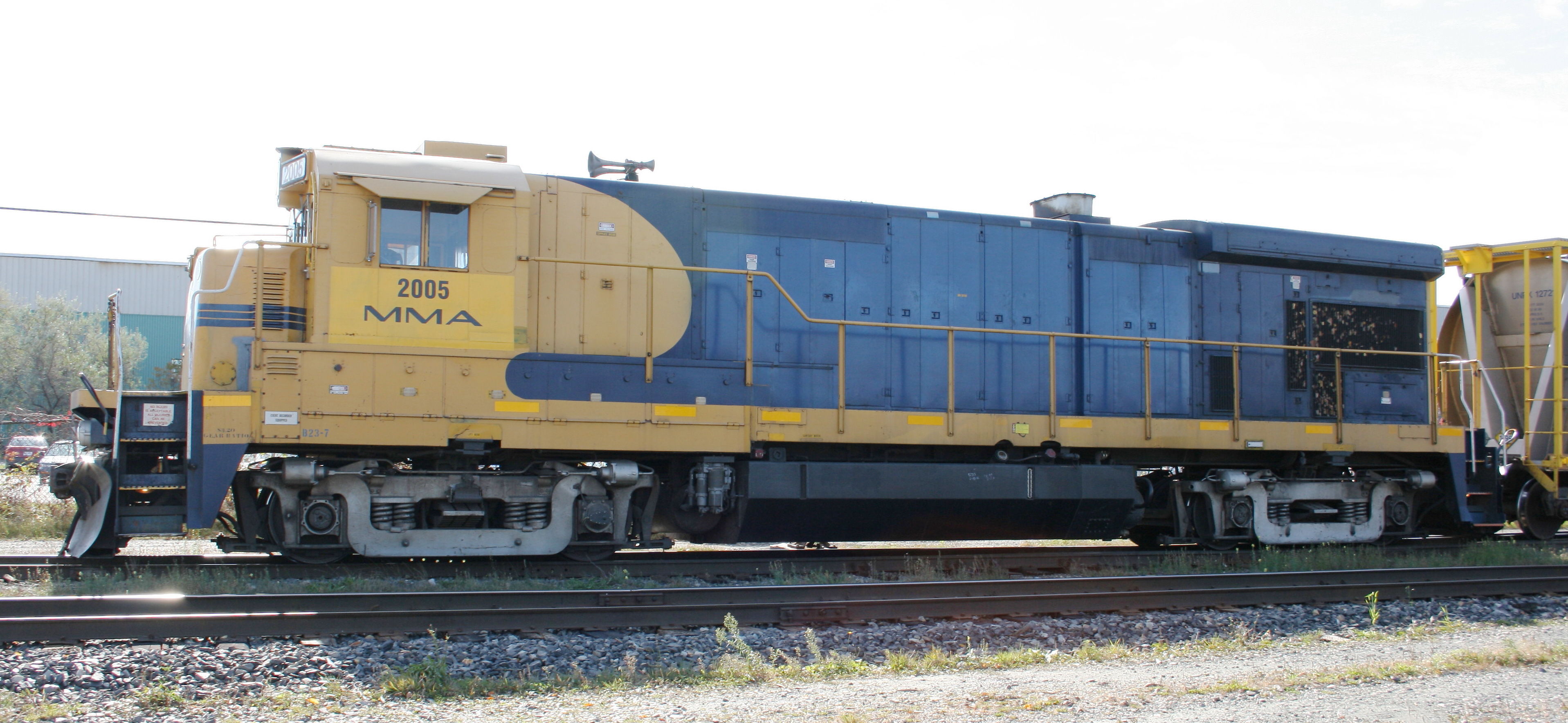
MMA #2005, a Phase 2b B23-7 originally built as ATSF #6386, seen in 2008.
In the mid 1970s, GE made a large number of changes to their locomotives aimed at improving reliability and ease of maintenance. A first batch of changes were incorporated into the last Universal series locomotives in 1975 and 1976. A second set of changes led to the introduction of the "1977 Series" or (as it was later known) Dash 7 series of locomotives at the end of 1976. The series continued GE's logical use of model names, with the first letter (B or C) denoting four or six axles, and the second two digits indicating horsepower. While the new series was characterized by several major design changes related to the air compressor location, lube oil and cooling systems, and electrical system, there were also a number of other smaller changes made to the prime mover and cab. Notably, the trouble-prone aluminum wiring used on a portion of Universal series locomotives was replaced with copper.
While four-axle Dash 7 units shared the same overall appearance as their Universal series predecessors, there was hardly a single body panel in common between the two series other than the cab and central hood doors. One of the most obvious changes was the elimination of the equipment air intake immediately behind the cab, as the equipment blower was moved to the radiator compartment at the rear of the hood. Additionally, unlike six-axle models, four-axle Dash 7 units extended the underframe by 2 feet compared to Universal units, resulting in noticeable "porches" at each end, and there were two more frame length/wheelbase changes made later in production. In addition to the length change, Phase 3 units adopted a thicker main underframe that increased the walkway height by 2" to 2.5", bringing it to about 70" (the height used on 4-axle Dash 8 units).
The wide radiator "wings" of the U36B were lowered and adopted for all Dash-7 models, and changes to the oil filter/cooler and air compressor were reflected in modified doors and intakes under the radiators. The break in the hood width previously near the radiators was moved to just behind the engine room doors, which themselves were moved closer to the cab. The cab sub-base doors on the conductor's side were also modified.
Four-axle Dash 7 production began with the B23-7 and B30-7, followed soon after by the B36-7. As with the U23B, the 12-cylinder B23-7 proved the most popular. The B18-7 (a replacement for the U18B) along with two intermediate models, the 12-cylinder B28-7 and 16-cylinder B33-7, were cataloged but never built. With the pending elimination of cabooses from freight trains, a unique variant (the BQ23-7) was built for SCL with the cab extended forward. In 1981, the 12-cylinder engine was uprated to 3,000 hp, resulting in the B30-7A, which was visually nearly identical to the B23-7. Two B30-7A variants - the slightly longer "B30-7A1" and cabless "B30-7AB" (as they were known among railfans) - were built for SOU and BN respectively. All 12-cylinder models were distinguished by six (rather than eight) engine room doors per side, but shared the same carbody and frame dimensions as 16-cylinder versions.
The improvements made by the Dash 7 series paid off. While some late model Universal series units saw service lives of less than ten years, many Dash 7 locomotives remained in service with their original owners for more than 20 years. Many continued in service on smaller railroads into the 2010's.
Phases
These phases are of my own making. In January and February 2021 I expanded my earlier phase descriptions with the addition of Phase 3b and 3d, and the separation of the original Phase 1a into Phases 1a through 1c. Six-axle versions followed a similar evolution; see GE C30-7, C30-7A, C36-7 Phases.
In several cases, two variations were offered concurrently before being standardized in later phases. For instance, not all orders immediately adopted the more rearward truck position of Phase 2a starting in early 1978, but those that didn't still had the modified rear stairwell side sheet that provided increased truck clearance (Phase 1b). Railroad diagrams are not reliable indicators of the dimensional changes between phases since they often continued to list the dimensions of earlier production.
Additionally, the dates I've found for units built for NdeM in Mexico show phase details being retained marginally later than for domestic production (shown by the dates in brackets).
Numbers correspond to the illustrations shown below.
| Phase | 1a | 1b | 1c | 1d | 2a | 2b | 2c | 2d | 3a | 3b | 3c | 3d |
|---|---|---|---|---|---|---|---|---|---|---|---|---|
| Dates | 1977-09 - 1978-04 | 1978-03 - 1978-05 | 1978-09 - 1979-01 | 1978-11 - 1979-03 | 1978-04 - 1978-11 (1979-12) | 1979-03 - 1979-12 | 1980-01 - 1980-06 (1981-02) | 1979-11 - 1980-06 (1981-01) | 1980-10 - 1981-05 (1981-12) | 1981-11 - 1982-02 (1982-05) | 1982-04 - 1982-09 | 1983-06 - 1985-08 |
| Rear stairwell side sheet 1 | Similar to front | Steeper slope (increased truck clearance) | Similar to front; narrower due to decreased frame length | |||||||||
| Fuel cutoff switch 2 | In walkway side frame above fuel filler (left side) below cab (right side) | In housing below side frame | ||||||||||
| Left side sill access hatches 3 | 4 hatches (B30-7) or 5 hatches (B23-7) each with 2 hinges + 3 bolts | 2 larger hatches, each with 3 hinges + 4 bolts (appeared on SP/SSW Phase 1a units) | 3 hatches | |||||||||
| Truck centers | 36' 2" equal distance from pilots | 37' 2" rear truck moved 1' rearward | 36' 8" (37' 10" for SOU B30-7A) rear truck 6" closer to pilot than front | |||||||||
| Phase | 1a | 1b | 1c | 1d | 2a | 2b | 2c | 2d | 3a | 3b | 3c | 3d |
| Jacking pads 4 | plain underside | flat metal plate on underside, revised attachment to sideframe | ||||||||||
| Air reservoir supports 19 | vertical U-channel with brace welded over fuel tank support | irregular sheets under fuel tank support | ||||||||||
| Hinged panels under radiators 5 | 3 bolts, straight bottom edge | central latch, notched bottom edge | ||||||||||
| Exhaust 6 | small stack, no silencer, narrow base | large silencer stack, wide base two stack heights used | ||||||||||
| Rear numberboards/lights 7 | flush numberboards and headlight, high class lights | raised numberboards and headlight, low class lights | ||||||||||
| Cab side windows 8 | 4 | 2 | ||||||||||
| Phase | 1a | 1b | 1c | 1d | 2a | 2b | 2c | 2d | 3a | 3b | 3c | 3d |
| Overall length | 62' 2" | 61' 2" (62' 4" for SOU B30-7A) | ||||||||||
| Walkway height | Approx. 67.75" | Approx. 70" | ||||||||||
| Left-side hatches under cab 9 | 2 narrow, 3 wide; small latches; bolted panel at front | 1 wide, 1 narrow, 3 wide; large latches; no bolted panel | ||||||||||
| Cab vent 10 | circular, on roof | rectangular, behind cab (inconsistent in Phase 3a) | ||||||||||
| Hood doors behind cab 11 | no bolted strip behind hood door closest to cab no drip rail over door | bolted strip added revised seams below door first 2 hood doors narrowed | drip rail added over door | |||||||||
| Phase | 1a | 1b | 1c | 1d | 2a | 2b | 2c | 2d | 3a | 3b | 3c | 3d |
| Long hood grabirons 12 | Closer spacing | |||||||||||
| High short hood | 6 grabirons | 5 grabirons, higher numberboards | ||||||||||
| Short hood left-side louvres 13 | Yes | No | ||||||||||
| Short hood headlight housing 14 | present on all units (blanked off when lights not installed) | present only with headlight installed | ||||||||||
| Hinged panels on hood ends 15 | No | Yes | ||||||||||
| Corner steps 16 | hinged panel behind top step | open behind top step | ||||||||||
| Phase | 1a | 1b | 1c | 1d | 2a | 2b | 2c | 2d | 3a | 3b | 3c | 3d |
Model variations
- BQ23-7 units were Phase 1d.
- B30-7A units were all Phase 3b through 3d.
- B36-7 units were Phase 3a and 3d, except for SSW 7770-7773, which were Phase 2c.
Other details
- Models of all phases may or may not have louvres under the cab on the right side.
- The doors under the forward section of the radiator may or may not have 3 narrow vertical intakes. Some units had such intakes retrofitted. 17
- Most Phase 2c units have a short exhaust silencer (as on concurrent 6-axle units); Phase 3 and some Phase 2c units have a taller exhaust silencer.
- Some B36-7 units were initially built with baffles over the rear radiator intakes, consisting of two large rectangular panels attached to the handrail and outer edge of the radiator "wings". 18 These were generally removed after a few years, although some retained the lower panel attached to the handrail.
Illustrations
These drawings illustrate typical early (Phase 1b) and late (Phase 3d) Dash-7 units built to CO and CR specifications. I elected to use a Phase 1b (rather than Phase 1a) variation to illustrate the revised rear stairwell side skirt. The Phase 3d drawing illustrates the radiator fan baffles that were applied to some B36-7's, and also shows the taller of the two later exhaust stack heights.
Pilot details, horns, and the coupler knuckle box (Phase 1b) or cab signal box (Phase 3d) behind the cab are railroad variations.
Click on the links to toggle between the two images.

Trucks
Four-axle Dash-7 units were built with three truck designs: FB-2, Type B and EMD GP (or Blomberg).
GE FB-2
The standard truck was GE's two-axle floating-bolster (or FB-2) truck, which used a 9' wheelbase and which had been introduced five years earlier in the four-axle Universal series. The design was very similar to the three-axle FB-3 truck introduced on six-axle units a few years prior, and it was relatively mechanically simple. The primary suspension consisted of springs above the axles and the secondary suspension involved the bolster "floating" on stacks of rubber pads resting on the middle of the truck frame. The secondary suspension allowed for a limited amount of lateral deflection.
Two foundries supplied FB-2 castings throughout Dash-7 production: Adirondack (identifiable by two holes between the axles and a single small hole above the right axle) and Rockwell (larger holes between the axles and an additional large hole above the right axle). Partway through Dash-7 production, the shock strut support was changed from a narrow triangular piece attached to the four upper bolt holes of the bearing housing to a larger circular plate that covered most of the bearing end cap. The last units also featured a revised sand line connection, with a stamped sheet and curved hose brace instead of several sections and channels welded together.
Type B
The Type B drop-equalized swing-hanger truck had been standard on early GE Universal units prior to the introduction of the FB-2 truck, as well as on most ALCO road units. The primary suspension was located inboard of the axles, with the truck frame supported on wide U-shaped equalizers. The bolster was supported by leaf springs in the center of the truck, which were in turn supported by swing hangers located behind the equalizers. The truck wheelbase was 9' 4", which, when combined with the clasp brakes, made the truck significantly longer overall than the FB-2.
I have not confirmed whether any Type B trucks on Dash-7 units were newly cast. However, it appears that at least a large portion were obtained from trade-ins, as many were cast by GSC, which had ceased production by that point. On whatever trucks that might have come from ALCO trade-in units, it appears GE installed new equalizers, as Type B trucks on all GE units used heavier-looking equalizers with a rounded (rather than slanted) top edge over the axle pedastals.
EMD GP
The EMD GP truck (commonly called the "Blomberg" truck) was used on a relatively small portion of Dash-7 production. It appears these too were taken from traded-in first-generation units (possibly EMD F-units) as the truck frames were generally old LFM castings.
While trade-in Type B trucks on EMD units reused the original (and robust) GE traction motors, GE did not do the same with EMD trucks. In order to accommodate larger GE 752 series traction motors, a portion of the Blomberg truck frame needed to be cut out and a revised traction motor suspension installed (not readily visible from the outside). GE changed the routing of the brake lines from above the truck frame to under the brake cylinders and wrapping around the swing hanger brackets. GE also modified the sand line brackets to a fabricated design similar to what was used on the FB-2. With an outside swing hanger / leaf spring secondary suspension and primary springs directly above the axles, this was apparently (from informal sources) the smoothest-riding of the three truck designs.
Although some four-axle Universal series units with Blomberg trucks retained clasp brakes, Dash-7 units received modified single-shoe brakes. EMD's own single-shoe GP truck (commonly called the "Blomberg M") used a shorter swing hanger and secondary suspension (rubber pads instead of leaf springs) to make room for the brake beam passing under the middle of the truck, with the brakes operated by a single brake cylinder. However, the modified trucks used on GE units retained the original leaf-spring secondary suspension, so in order to use single brake shoes, the bottoms of the brake levers were attached to the safety strap underneath the leaf spring, with each shoe operated by a brake cylinder.

Railroad Variations
Family Lines / Seaboard
The most distinctive model in the entire Dash 7 series was the BQ23-7, with "Q" standing for "Quarters" cab. Ten were built for SCL in late 1978 - early 1979. The BQ23-7 featured an unusual and significantly enlarged cab that took up the entire space normally occupied by the short hood, and was intended to provide space for a 5-person crew without a caboose. The high front windows limited downward visibility when switching and the lack of a short hood raised concerns about safety in a collision, apparently giving the model an unfavourable reputation among crews. Successor CSXT converted the units to B-units in 1993, plating over the windows. Other than the cab, the units were the same as concurrent B23-7 production.
The remainder of the four-axle Dash 7 units ordered by LN and SCL were off-the-shelf B23-7 and B30-7 units. The B30-7's and LN B23-7's had GE FB-2 trucks while SCL B23-7's (including the BQ23-7) were built with trade-in EMD Blomberg trucks. Common spotting features included flat pilot end plates, a Leslie S5T-R horn, and a nose-mounted headlight. Early units had a Gyralite mounted in the upper light position on the cab. A single unit ordered by Providence & Worcester (PW 2201) was tacked on to the first order of LN B23-7's.
Two batches of B36-7's arrived in 1985, following the consolidations that resulted in the 1982 formation of the Seaboard System Railroad. These units had cab-mounted headlights and K5LA horns previously typical of Chessie System units.
Southern
Southern's first Dash 7 units were an order of B23-7's that arrived in late 1978, with Phase 1c spotting features. Externally, they carried over all the same characteristics as Southern's last order of U23B's, including a high short hood; horns and large plows at both ends; lowered pilot drop steps; a fuel tank with a central filler and built-in oil retention tank at the rear; platform lights along the top sides of the hood; and flag brackets on the hood corners. Unusually for Southern units of the time, they were delivered with K5LA horns. While these were promptly swapped on several units for Southern's trademark Nathan P5, the K5LA would later become standard on Norfolk Southern locomotives by the 1990s.
In 1981, Southern took delivery of additional B23-7's as well as an order of B36-7's (with Phase 3a features). Other than the model-specific differences (six vs. eight tall engine room doors, side-mounted radiator fan baffles on the B36-7) they were virtually identical externally.
The following year, Southern purchased a unique variant of the B30-7A, unofficially known as the "B30-7A1". (I haven't confirmed the model name with a builder's plate, but Norfolk Southern diagrams list the model as B30-7A). While other four-axle Dash 7 units had the equipment blower located at the rear of the radiator compartment, the "B30-7A1" adopted the forward-mounted blower used on six-axle units, using the same square air intakes near the front of the hood as on the C30-7. The frame was lengthened by 14" to accommodate the revised blower location, which also resulted in a longer fuel tank; these were the only Southern Universal or Dash 7 units that used an offset (rather than central) fuel filler.
References
CSXTHS. (2020). The BQ23-7 - Unique to CSXT. Journal of the CSXT Historical Society 8 (3), p. 5-6.
Davis, W. (2014). General Electric's 1977 Series Locomotives. Retrieved December 2019 from http://railroadlocomotives.blogspot.com/2014/01/general-electrics-1977-series.html
Foster, Gerald. (1996). A Field Guide to Trains. New York, NY: Houghton Mifflin.
General Electric. Locomotive Service Manual for Series-7 Road Locomotives. GEK-30150, 1978-08.
Moyers, J. T. (1974, April). GE's new Floating Bolster Truck. Railroad Model Craftsman, 37.
The Diesel Shop. (2011). General Electric B23-7 & BQ23-7. Retrieved December 2014 from http://thedieselshop.us/GE_B23-7.HTML.
The Diesel Shop. (2011). General Electric B30-7 & B30-7A. Retrieved December 2014 from http://thedieselshop.us/GE_B30-7.HTML.
The Diesel Shop. (2011). General Electric B36-7. Retrieved December 2014 from http://thedieselshop.us/GE_B36-7.HTML.