
Locomotive Descriptions and Phases - ALCO/MLW FA and PA series
In 1946, ALCO (in partnership with General Electric) introduced a series of locomotive models equipped with their new 244-series engine aimed at three primary markets: A freight cab unit (the FA-1); a passenger cab unit (the PA-1); and a road switcher (the RS-2). In 1950, the models were updated (as the FA-2, PA-2 and RS-3 respectively) to include various mechanical improvements as well as a wider array of options for different service types.
Background and 244 Engine Development
ALCO's pre-war passenger locomotives had been powered by a pair of 1,000-horsepower turbochared 539 series engines, which used an inline 6 design. While this engine established a solid reputation in switching service, its low power-to-weight ratio limited the possibility of further horsepower increases, and it was not well suited to sustained high power applications as opposed to the brief surges of power typical in switching service.
As a result, and in response to the success of the EMD FT introduced in 1939, ALCO began work on a new higher-speed 4-stroke V engine in 1940, designated 241. Three 12-cylinder 241 engines were built for testing in an A-B-A set of experimental cab units, known as the "Black Maria" units due to their black paint scheme. Progress was slow, and when several weaknesses became apparent during testing in 1944, ALCO started work on a second engine design to similar specifications but aimed at ease of mass-production, known as the 244. The first 244 engine was ready for testing in 1945, and work on the 241 engine (initially intended to remain as a stopgap) was abandoned soon afterward.
With the market for cab units already reaching its peak, ALCO pushed for an extremely rapid entry into service by the beginning of 1946. In late 1945, before testing on the 244 had fully concluded, construction began on the first locomotive models intended to use the new engine, and the first FA-1 entered service in early 1946. Problems soon arose with the cast crankshafts, which were replaced with forged versions later that year; those also initially suffered failures due to manufacturing defects. Issues with the exhaust manifold and air-cooled turbocharger (adopted from the 241) remained unresolved, involving both mechanical reliability and acceleration characteristics. In effect, much of the testing of the new engine design occured on locomotives already in service, with many components and entire engine blocks replaced under warranty. In some cases (such as on the ATSF and DRGW), PA units were demoted from the premier passenger trains for which they were initially intended, replaced by EMD F-units.
After extensive development and incremental improvements, the air-cooled GE turbocharger was finally replaced by a GE-designed water-cooled turbo in June 1953, followed by an ALCO-designed version in September 1954. Externally, the change was evident in the exhaust stack being centered and crosswise, rather than offset and lengthwise. By this point, sales of cab units had slowed considerably in favour of road switchers, and only a few dozen FA-2 and PA-2 units came so-equipped from the factory. However, most earlier units were promptly upgraded with the new turbocharger design. Once initial teething issues were overcome the FA and PA series generally provided decent service, with some remaining in use up to the late 1960s.
Model Descriptions
ALCO/MLW FA-1

CN #9400, an MLW FA-1 preserved at Exporail, seen in 2001. This was the first road freight diesel locomotive built in Canada.
Designed for road freight service, the FA-1 rode on 4-wheel Type B trucks and was powered by a 1,500-horsepower, 12-cylinder 244 engine. Typical of road locomotives of the time, the carbody was a streamlined truss-frame design. A cabless "booster" model (the FB-1) was also produced. They were initially known simply as the "1,500 hp freight locomotive"; the simplified model names were retroactively applied later in the 1950s.
The FA-1 was distinguished from later units (and from the longer PA-1) by a relatively short length, and by the radiator shutters and fan located at the very end of the carbody. As it was intended for freight use, it did not have room inside the carbody for water tanks or a steam generator for passenger service (although the absence of the cab on the FB-1 did provide sufficient room in theory). The underframe between the trucks contained the fuel tank, flanked by the air reservoirs and battery boxes.
Compared to other cab units of the era, the FA was visually distinguished by relatively square front styling, with a vertical and nearly flat-topped "nose". The busy appearance of ALCO's earlier cab units (with multiple portholes and roof vents) was replaced with clean, largely horizontal lines. The upper sides of the carbody had a continuous grill interrupted by radiator shutters near the rear, above which was a single large radiator fan. A single exhaust stack was located in front of the radiator fan; it was offset and lengthwise with the initial air-cooled turbocharger, and centered and crosswise with the later water-cooled turbo retrofitted to many units.
All variations had a side carbody door centered in the middle of the carbody, with A units having the cab side door above the front truck. Dynamic brakes (when present) were identifiable by a long, slightly raised housing on the front half of the roof.
ALCO PA-1, PA-2
The PA series, initially known as the "2000 hp passenger locomotive", was to become one of the most aesthetically admired locomotives of its era. Built to a similar overall design to the FA-1, the carbody and "nose" were significantly stretched and rode on drop-equalized A-1-A trucks with a very generous wheelbase (15' 6"), resulting a long and sleek appearance despite a relatively modest 63-foot length. The intakes along the top were shrouded with horizontal bars and a curved trim piece extending from the top of the windshield, both of which were retained over most of production.
Mechanically, the PA-1 was powered by a 16-cylinder version of the 244 engine, with correspondingly longer radiator shutters near the rear. A steam generator was located in the rear of the carbody with a steam line extending down behind the rear steps. Wheels were either 40" or 42", with changes to the secondary suspension in the trucks to maintain the same ride height with either size. Despite not all axles being powered, the turbocharged engine and robust GE electrical components of the PA-1 initially found favour on mountainous routes, where it outperformed EMD's competing E units.
Compared to the FA-1, the bottom of the underframe and the side sill were 1" higher, but the two lower carbody side panels were each a half-inch shorter in height, such that the overall cab and carbody height was the same. The area between the trucks was the same as on the FA-1 (housing the fuel tank, air reservoir and battery boxes) but was covered by a full-height shroud.
The introduction of the first production PA units in late 1946 (an A-B-A set for ATSF) was the subject of much fanfare. Marketed as the "6000" locomotive (for the set's total horsepower), they were celebrated in a ceremony at the Schenectady plant and displayed in New York City. After delivery to ATSF, they were displayed again in Chicago and Los Angeles prior to entering testing and regular service.
In 1950, the PA-1 was replaced by the PA-2. An updated main generator saw the horsepower increased from 2,000 to 2,250, but the exterior appearance remained virtually unchanged. Late in PA-2 production, the slatted grills were replaced with Farr intakes.
While the PA series was demonstrated in Canada, none were built by MLW.
ALCO/MLW FA-2, FPA-2
Unlike the PA-2 (which was a modest update over the PA-1) the FA-2 received significant changes from the FA-1, chiefly to make room for an optional steam generator for passenger service. Horsepower was also upped from 1,500 to 1,600. Prior to the "FA-2" model name, it was known as the "1,600 hp freight-passenger locomotive".
Compared to the FA-1, the overall length was increased by 2 feet, and the radiators were shortened and moved forward to leave an additional 5 to 6 feet of space at the rear of the carbody. To make room for water tanks between the trucks, the battery boxes were moved to a compartment under the cab (visible in the addition of louvered access panels ahead of the cab steps) and the air reservoirs were moved to the inside rear of the carbody. An air cooling manifold (an extension of the pipe between the air compressor and air reservoirs) was placed on the outside back wall of the carbody.
Passenger versions of the FA-2 and FB-2 were known as the FPA-2 and FPB-2 respectively, and placed a steam generator in the extra room at the rear of the carbody and a combination fuel/water tank that took up all available space between the trucks. However, the majority of production consisted of the freight-only FA-2, and the relatively small crosswise fuel tank left several feet of empty space between the trucks.
Several other more minor changes from the FA-1 were made as well. FA-2's were built with angled numberboards in a simplified rectangular housing, as opposed to either side-mounted numberboards or a more rounded angled housing used on the FA-1. The bottom of the underframe and carbody were raised by 1" compared to the FA-1, bringing the height in line with the PA series. The batten strip above the side grills was narrowed (from about 6.5" to about 5.25") and was held in place by a single row of screws (in place of two rows). The draft gear carrier, which on the FA-1 and PA series was a separate housing bolted in place, was welded as an integral part of the underframe on the FA-2.
FPA-4
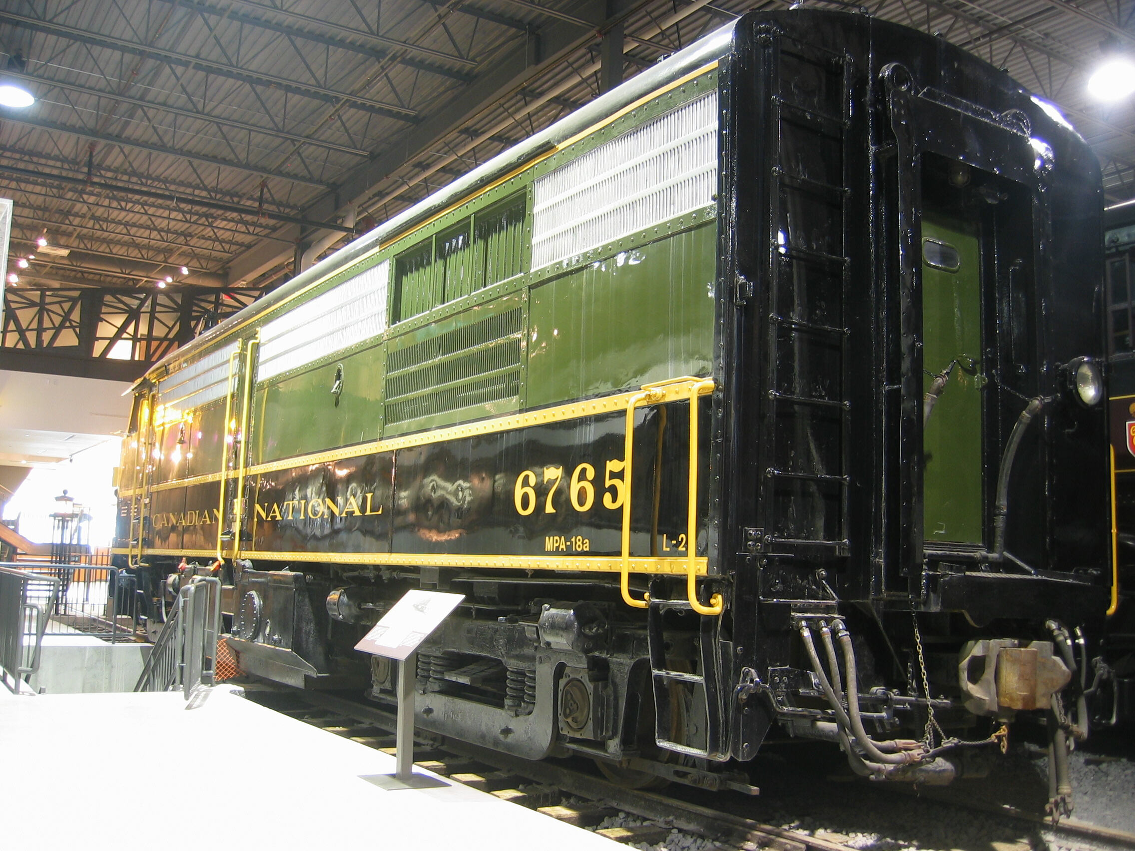
CN FPA-4 #6765, seen preserved at Exporail in 2006.
While late-production 244 engines addressed many of the design's initial reliability issues, the engine was ultimately replaced (after thorough testing) by the 251 series engine in 1956. ALCO apparently catalogued an updated model to be known as the FA-4, but none were built.
However, in 1958, MLW built several dozen FPA-4 and FPB-4 units for Canadian National, powered by a 1,800 horsepower 251 engine. Externally, it was substantially similar to the late ALCO FA-2, and even more similar to the MLW FPA-2's that immediately preceded it on the CN roster. The most obvious difference was the additional air intake under the radiator shutters, which were added after the air cooling pipe manifold was moved from the outside back wall to inside the carbody. Although the 251-series engine was longer than the 244 engine, the carbody and roof hatch dimensions remained the same. The fuel and water tanks on the FPA-4 were unique compared to other ALCO FA units (although some CN FPA-2 units were rebuilt with similar tanks) and the coupler pockets and draft gear were a welded design that differed from those used in earlier production.
As built, the FPA-4 (along with earlier MLW FA unit production) had a few modifications to deal with Canadian winters. A winterization hatch was located over the front of the radiator fan, which could be set to direct warm air back into the engine compartment. The bell was located on the cab roof instead of in the underframe behind the front coupler.
The culmination of the FA series design, the FPA-4 and FPB-4 enjoyed a significantly longer service life than most earlier models thanks in large part to the reliability and parts availability of the 251 engine. They remained in service up to 1989 on successor VIA Rail, and were only retired when they didn't meet new requirements for an electronic Reset Safety Control (RSC) system on lead locomotives in Canada. Today the FPA-4 and FPB-4 account for roughly half of all preserved FA-series locomotives.
Phases
FA-1
There were no major production variations that would warrant phases, but there were a number of changes that occurred early in production.
The first few units (two ALCO demonstrators and the first 34 production units built for GM&O) had the headlight mounted below the seam on the nose, and had a curved trim piece behind the side cab windows. The ALCO demonstrators also had horizontal side grills and fairings over the fuel tank and air reservoirs, similar to those used on the PA. All later units abandoned the curved side trim and used a thinner wire grid for the side grills. The headlight was moved to the top of the nose, providing enough space for an optional second light housing underneath.
In addition to the earliest design changes, there were a few other minor variations:
- The center side ladder on early units had an extension at the bottom designed to line up with the side fairings over the fuel tank; the ladder extension was shortened on later units (as was the side fairing that was retained on the PA-1).
- Numberboards were either a small side-mounted housing with integrated class lights, or a larger angled housing with rounded corners and class lights above. Some units had a central numberboard above the cab.
- Some units were built with higher-clearance pilot sides, with the bottom edge of the side sheets (below the step notch and uncoupling lever) about 2" higher than the standard pilot.
- There were minor variations in the air piping, including the presence or absence of a cooling manifold on the right side; I haven't been able to confirm what variations were present as-built.
FA-2 and FPA-2
FA-2 units did receive a few minor production changes that would warrant phase distinctions, with significant overlap in the production dates of Phases 1b and 2.
| Phase | 1a | 1b | 2a | 2b |
|---|---|---|---|---|
| Dates | 1950-10 - 1951-05 | 1950-12 - 1953-05 | 1951-06 - 1953-07 | 1953-06 - 1956-06 |
| Battery box louvers | Vertical | Horizontal | ||
| Side air intakes | Square wire grid | Farr (3 rows of stamped vertical slots) | ||
| Turbocharger | Air-cooled (lengthwise stack) | Water-cooled (crosswise stack) | ||
As with the FA-1, some models were built with higher-clearance side sheets on the pilots. A number of A-units were also equipped with hinged front coupler shrouds, which in general were promptly removed. Later versions usually had several plugs along the bottom edge of the fuel tank. Multi-chime air horns were just being introduced as the FA-2 entered production, and some variations were so-equipped from the factory.
PA-1, PA-2
While there were no major changes during PA-1 production, there were a few minor variations:
- Early units had the side fairing between the trucks extending down to the bottom of the fuel tank; on later units, the fairing height was reduced by about 4" to the height of the bottom step, uncovering a portion of the air reservoirs.
- Many earlier-production units had the front coupler cut lever operated by a stylized horizontal bar on the surface of the pilot; later units reverted to the simpler design of the FA-1 which housed a standard lever end inside a rectangular recess.
The PA-2 is commonly divided into two phases depending on the upper carbody intakes, which were also the primary distinguishing feature from the PA-1.
Early PA-2 units continued to use horizontal top side grills of the PA-1, but the air intakes underneath the grills were modified. Behind the cab, the PA-2 had an opening right behind the curved trim piece (previously present only on some PA-1's, generally with dynamic brakes), which exposed the top of the main truss member. The openings on either side of the central door were blocked off, with the large opening behind the door replaced by a single small, square opening.
In 1952 the horizontal side grills were replaced with Farr grills with three rows of stamped vertical slots. The porthole at the rear of the carbody and the curved trim piece behind the cab were eliminated. The last units built in 1953 had another updated main generator and water-cooled turbocharger; these are sometimes incorrectly referred to as a "PA-3", a designation that was possibly reserved for a 251-engined model that was never built.
Unlike the FA-2, the PA-2 retained the wider upper batten strip above the air intakes with 2 rows of screws (although the bottom row was obscured by the earlier intake grills) and the 45-degree numberboards retained the rounded housing rather than the simpler rectangular design introduced on the FA-2.
PA-2 Phases
| Phase | 1 | 2a | 2b |
|---|---|---|---|
| Dates | 1950-03 - 1952-05 | 1952-05 - 1953-05 | 1951-06 - 1956-06 |
| Side air intakes | Square wire grid | Farr (3 rows of stamped vertical slots) | |
| Turbocharger | Air-cooled (lengthwise stack) | Water-cooled (crosswise stack) | |
Options
Various railroad-specific options were available across all the models:
- Dynamic brakes: Contained in a long, slightly raised housing along the center front section of the roof
- Couplers: The majority of PA units were built with "tightlock" Type H couplers suited to passenger service. Many PA's and a few FA's were built with a coupler shroud on the front pilot (often promptly removed) and some PA's had a hidden coupler mechanism that could retract the coupler behind the pilot.
- Lights: An oscillating Mars light required a second light housing below the main housing on the front; the main headlight was often relocated to the lower position.
- Number boards: On the FA-1 and PA series, standard number boards were small housings on the side of the nose, with the classification lights integrated at the front of the housings. Larger 45-degree numberboards in a rounded housing were available, in which case the classification lights were located above them. (FA-2 units used a rectangular angled numberboard housing).
- Horn: As-built, many had Wabco E-2 horns, either single or dual (in the latter case with the second horn reversed). A significant minority had slightly larger Leslie A-200 horns. Later in FA-2 production, several early multichime horns appeared, such as the Leslie A-125-3F, S-3J and early S-3L. At least one NYC PA-2 builder's photo shows a rare Wabco multi-chime horn (possibly an E-2B-2). The last PA units built for SP had Nathan M5 horns.
Dimensions
ALCO diagrams have occasionally led to misunderstandings about the locomotive length, as they list both the length between the coupler pulling faces (the standard measure) as well as the length over the outside edge of the coupler knuckles. However, most FA and PA production followed the same dimensions.
In all cases, the overhang on the A units was larger at the front than the rear, meaning that B units (which used the rear overhang at both ends) had the same truck centers and carbody dimensions but a shorter overal length.
Below are dimensions for FA models as well as for the related PA and PB models.
| Model | Length between coupler pulling faces | Truck centers | Carbody roof height |
|---|---|---|---|
| FA-1 | 51' 6" | 27' 2" | 14' 0" |
| FB-1 | 50' 2" | ||
| FA-2, FPA-2, FPA-4 | 53' 6" | 29' 2" | |
| FB-2, FPB-2, FPB-4 | 52' 8" | ||
| PA-1, PA-2 | 65' 8" | 34' 2" | |
| PB-1, PB-2 | 63' 6" |
Measurements and Illustrations
The FPA-4 was the first ALCO/MLW cab unit I drew in 1:18, and my drawings are based on a combination of measurements I made of CN #6765 preserved at Exporail as well as ALCO FA-2 mechanical diagrams.
The center side door, sand hatches and fuel / water tanks are centered between the trucks, and the inner truss structure is also symmetrical between the truck centers. The exact location of the side seam screws varies slightly between units, although the 4" spacing is consistent. Most dimensions are the same between the two sides; the left side is illustrated as that was the side that was accessible for measuring on CN #6765.
Most preserved units have the steam generator piping either removed (units in operation) or modified (CN #6765 at Exporail), so to draw the steam lines, I did an extensive search of older photos of units in operation on CN and VIA, as well as relying on one of my own photos of the steam pipes on a GMD FP9Au; even so, the upper part of the steam pipes are a bit of a stand-in based on what I could decipher from photos.
The drawing illustrates the general appearance of FPA-4's after modifications by CN and VIA, but with the steam lines still intact. Among components with dimensions listed, the front fuel filler, the ladder on the end of the carbody, and the large circular panel on the water tank were absent on the units as-built.
B units were 10" shorter (52' 8") with the length removed between the front coupler and truck, making them symmetrical front-to-back. Two steam generators were located at the front (rather than a single one at the rear); the rooftop hatch over the steam generators was approx. 3" longer than on A units (approx. 75" instead of 72") and was located farther inboard from the end of the carbody. Most of the dimensions and hood components from the front truck rearward were the same between the FPA-4 and FPB-4.
References
Much of the information above has relied on original reseach (such as extrapolating from photos) or on indirect sources of information such as forum discussions. Nevertheless, I've attempted to list the main sources of information I used in establishing my own descriptions and drawings. Historical information has come largely from Richard Steinbrenner's The American Locomotive Company: A Centennial Remembrance, which by all accounts is the finest single source of ALCO's history and production.
In addition to the ALCO mechanical drawings listed, I used a number of other drawings of separate components to make my own drawings.
ALCO 244 Prime Mover [Online discussion]. (2021). Retrieved February 2022 from https://cs.trains.com/trn/f/741/t/286786.aspx
American Locomotive Company. (1946). Erecting Apparatus Drawing 4311S94850 (FA-1). [Drawing].
American Locomotive Company. (1946). Erecting Apparatus Drawing 4311S94900 (PA-1). [Drawing].
American Locomotive Company. (1948). Erecting Apparatus Drawing 4311S96460 (PA-1). [Drawing].
American Locomotive Company. (1951). Erecting Apparatus Drawing 4311S900280 (FA-2). [Drawing].
Bayer, G. Alco/MLW FA-2 Master Class. Retrieved February 2022 from https://rapidotrains.com/alco-mlw-fa-2-master-class
City of Vancouver Archives. Walter E. Frost fonds, Locomotives [photo search]. Retrieved Feburary 2022 from https://searcharchives.vancouver.ca/informationobject/browse?subjects=413524&collection=474202&topLod=0&sort=alphabetic&sortDir=asc
Denver Public Library. Digital Collections [photo search]. Retrieved March 2022 from https://digital.denverlibrary.org/digital/search/searchterm/alco
Komanesky, J. (2011). Alco PA & PB roster. Retrieved February 2022 from https://www.thedieselshop.us/AlcoPA.HTML
Komanesky, J. (2014). Alco / MLW FA-1 & FB-1 roster. Retrieved February 2022 from https://www.thedieselshop.us/AlcoFA1.HTML
Komanesky, J. (2021). Alco / MLW FA-2 & FB-2 roster. Retrieved February 2022 from https://www.thedieselshop.us/AlcoFA2.HTML
Lucas, S. (2016, January). Rapido MLW PA-4 in HO. Model Railroad News. Retrieved February 2022 from https://modelrailroadnews.com/rapido-mlw-pa-4-in-ho/.
Martin, G. (1992, August). PRR FA-2's, Detailing Life-Like. Mainline Modeler, 20-24.
Montreal Locomotive Works Ltd. (1952). Operating Manual TP-402 for 1600 hp diesel-electric road freight-passenger locomotive.
Peck, D. (1984, January). ALCO FA-2. Mainline Modeler, 40-51.
Steinbrenner, R. T. (2011). The American Locomotive Company: A Centennial Remembrance. Warren, NJ: On Track Publishers, LLC.