
Locomotive Descriptions and Phases - GE C30-7, C30-7A, C36-7
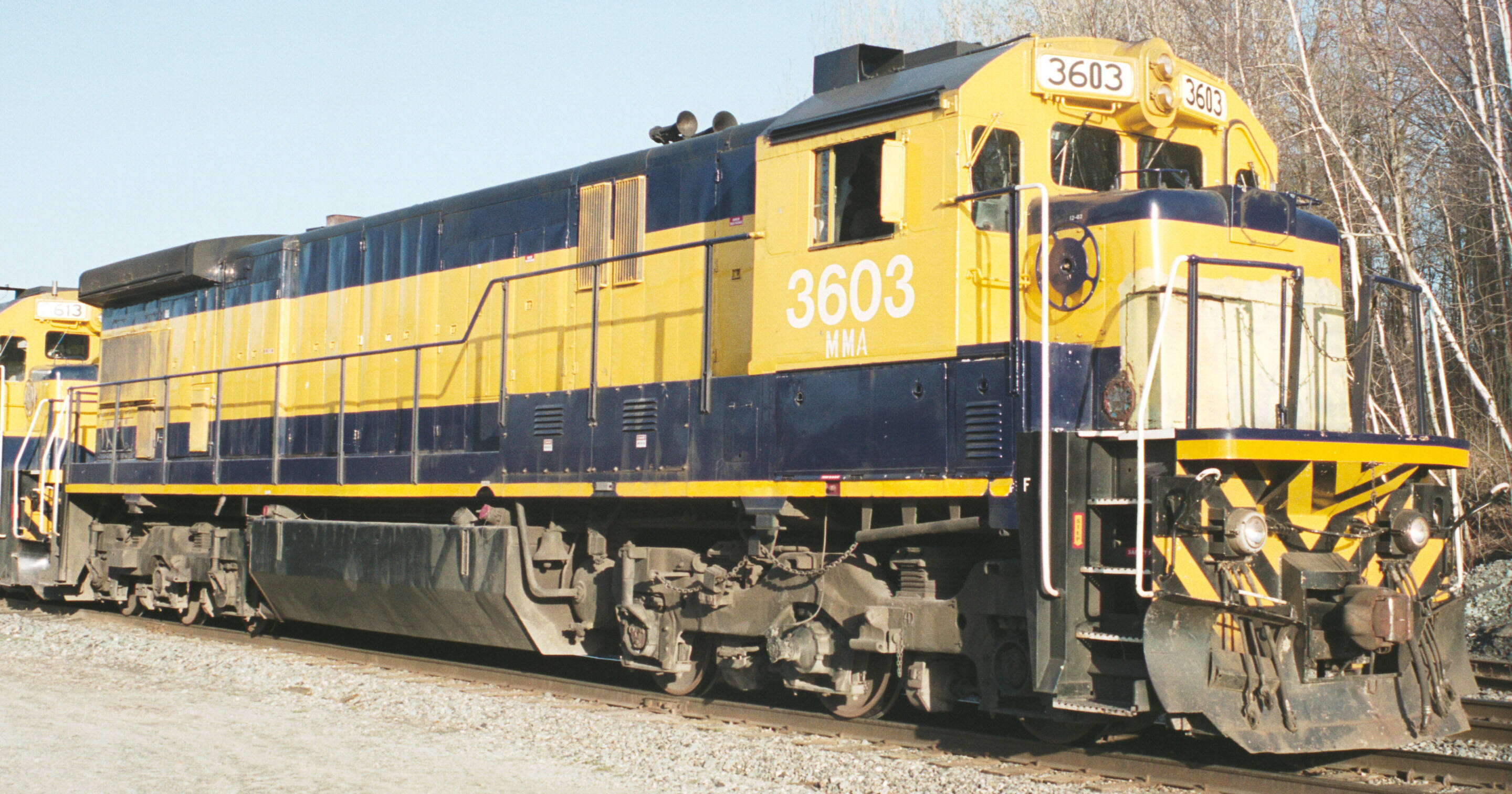
MMA #3603, a Phase 1a former ATSF C30-7 seen in 2006.
In the mid 1970s, GE made a large number of changes to their locomotives aimed at improving reliability and ease of maintenance. A first batch of changes were incorporated into the last Universal series locomotives in 1975 and 1976. A second set of changes led to the introduction of the "1977 Series" or (as it was later known) Dash 7 series of locomotives at the end of 1976. The series continued GE's logical use of model names, with the first letter (B or C) denoting four or six axles, and the second two digits indicating horsepower. While the new series was characterized by several major design changes related to the air compressor location, lube oil and cooling systems, and electrical system, there were also a number of other smaller changes made to the prime mover and cab. Notably, the trouble-prone aluminum wiring used on a portion of Universal series locomotives was replaced with copper.
The mechanical and electrical improvements made to the Dash 7 series did not result in many major external differences from the Universal series - at least, not at first glance. However, though the carbody and frame retained the same proportions, there was hardly a single body panel in common between the two series other than the cab and central hood doors. The wide radiator "wings" of the U36C were lowered and adopted for all Dash-7 models, and changes to the oil filter/cooler and air compressor were reflected in modified doors and intakes under the radiators. The break in the hood width previously near the radiators was moved to just behind the engine room doors, which themselves were moved closer to the cab. Changes to the electrical system resulted in different cab sub-base doors on the conductor's side and battery boxes moved closer to the cab on the engineer's side.
Initially, six-axle Dash 7 models included the C30-7 (by far the most popular) and C36-7, which replaced the U30C and U36C respectively. Several models were offered but never built, including two 12-cylinder models (the C23-7 and C28-7) that replaced the U23C, as well as the C33-7. In 1984, the 12-cylinder FDL engine was uprated to 3000 horsepower, resulting in the creation of the C30-7A, of which Conrail was the only buyer. Compared to the two other models, it was distinguished by six (rather than eight) engine room doors per side.
The improvements made by the Dash 7 series paid off. While some late model Universal series units saw service lives of less than ten years, many Dash 7 locomotives remained in service with their original owners for more than 20 years. Although they did not remain in service quite as long as EMD's competing SD40-2, many were sold to smaller railroads or exported to South America and continued in service into the 2010's.
Phases
These phases are of my own making. Some units built for NdeM in Mexico retained phase details slightly later than for domestic production (shown by the dates in brackets). Four-axle versions followed a similar evolution; see GE B23-7, B30-7, B30-7A, B36-7 Phases.
Numbers correspond to the illustrations shown below.
| Phase | 1a | 1b | 1c | 2a | 2b | 2c | 2d | 2e | 2f |
|---|---|---|---|---|---|---|---|---|---|
| Dates | 1976-09 - 1978-06 | 1978-06 - 1979-03 | 1979-04 - 1979-11 | 1979-11 - 1980-07 (1981-01) | 1980-05 - 1980-10 | 1981-03 - 1981-10 | 1982-01 - 1982-03 | 1982-05 - 1983-01 (1985-01) | 1984-05 - 1987-06 |
| Fuel cutoff switch 1 | In walkway side frame above fuel filler (left side) below cab (right side) | In housing below side frame | |||||||
| Left side sill access hatches 2 | 5 hatches, each with 2 hinges + 3 bolts | 2 larger hatches, each with 3 hinges + 4 bolts | 3 hatches | ||||||
| Hinged panels under radiators 3 | 3 bolts, straight bottom edge | central latch, notched bottom edge | |||||||
| Air reservoir supports 4 | vertical U-channel with brace welded over fuel tank support | irregular sheets under fuel tank support | |||||||
| Exhaust 5 | small stack, no silencer, narrow base | large stack/silencer, wide base | |||||||
| Rear numberboards/lights 6 | flush numberboards and headlight, high class lights | raised numberboards and headlight, low class lights (appeared on NW Phase 1c units) | |||||||
| Cab side windows 7 | 4 | 2 | |||||||
| Phase | 1a | 1b | 1c | 2a | 2b | 2c | 2d | 2e | 2f |
| Left-side hatches under cab 8 | 2 narrow, 3 wide; small latches; bolted panel at front | 1 wide, 1 narrow, 3 wide; large latches; no bolted panel | |||||||
| Cab vent 9 | circular, on roof | rectangular, behind cab (inconsistent in Phase 2c) | |||||||
| Hood doors behind cab 10 | no bolted strip behind hood door closest to cab no drip rail over door | bolted strip added revised seams below door air intake moved rearward first 2 hood doors narrowed | drip rail added over door | ||||||
| Long hood grabirons 11 | Closer spacing | ||||||||
| Short hood left-side louvres 12 | Yes | No | |||||||
| Short hood headlight housing 13 | present on all units (blanked off when lights not installed) | present only with headlight installed | |||||||
| Hinged panels on hood ends 14 | No | Yes | |||||||
| Corner steps 15 | hinged panel behind top step | open behind top step | |||||||
| Phase | 1a | 1b | 1c | 2a | 2b | 2c | 2d | 2e | 2f |
Other details
- The doors under the forward section of the radiator may or may not have 3 narrow vertical intakes. Some units had such intakes retrofitted. 16
- Some later-production units (notably ATSF and Family Lines units) were built with an oil retention tank integrated into the rear of the fuel tank, with the rear fuel filler and gauge moved forward and a visible seam near the rear of the fuel tank.
Illustrations
These drawings illustrate typical early (Phase 1a) and late (Phase 2f) Dash-7 units built to Conrail specifications.
Click on the links to toggle between the images.


Trucks
While all six-axle Dash-7 units rode on GE's "floating bolster" FB-3 truck, two different truck castings were used with three different brake arrangements. Adirondack castings had a beefier profile with casting holes near the outer axles, while Rockwell castings had holes centered between the axles (the pattern previously cast by GSC). Single-shoe brakes were available with the brake cylinders positioned either low between the axles or high at the top corners. Clasp brakes had high-mounted brake cylinders with a third brake cylinder added above the middle axle.
Two wheel bearing designs were used: Hyatt cylindrical oil-lubricated bearings (commonly seen on older EMD units) and Timken tapered greased bearings with exposed bearing caps. Partway through Dash-7 production, the shock strut support on versions with Timken bearings was changed from a narrow triangular piece attached to the four upper bolt holes to a larger circular plate that covered most of the bearing end cap. The last units also featured a revised sand line connection, with a stamped sheet and curved hose brace instead of several sections and channels welded together.
The axle spacing on FB-3 trucks was uneven, with the center axle offset by 2 inches to provide room for the center traction motor. On most units, the trucks were arranged "elephant-style" with the middle traction motor facing rearward (toward the long hood) on both trucks. The only exception I've come across is NW C30-7's, which had clasp-brake trucks with the rear truck reversed (the middle traction motor facing the fuel tank).

Railroad variations
Conrail
Conrail units (C30-7, C30-7A and C36-7) were all built with high-clearance 4-step end platforms, in place of the more common 5 steps. Although Conrail C36-7's were built at the same time as MP and NW units, which had dynamic brakes in a new housing behind the cab, CR units continued to use the older design with the dynamic brake grids located behind the radiator intakes. The C30-7A had six tall engine room doors per side but was otherwise similar in appearance to Conrail's C36-7's; both were built with classification lights in square housings. All had a cab signal box on the left side behind the cab and were built with high-mounted brake cylinders.
Norfolk & Western / Norfolk Southern
NW C30-7's and C36-7's had trucks with clasp brakes, generally with Adirondack castings. The first batch of C30-7's (NW 8003-8037) had the bell on the long hood end, and all units had a Leslie S-5T horn, placed near the cab but with 3 bells oriented toward the long hood. Early units had 4-step end platforms while late C36-7's had 5 steps. A coupler knuckle basket was located on the walkway on the left side behind the cab.
Soon after delivery, NW #8501 (part of the first order of C36-7's, numbered 8500-8505) was modified with higher-capacity dynamic brakes relocated from inside the radiator compartment to a boxy housing behind the cab, eliminating the need for the radiator fan to double as a dynamic brake fan.
The last C36-7 order (#8531-8542) occurred after the Norfolk Southern merger; they were ordered by NS but delivered with NW sub-lettering. Along with C39-8's #8550-8551, they were among the first new locomotives to be delivered in Norfolk Southern paint. They used the revised dynamic brake setup previously installed on #8501, and were also built to updated NS specifications (single-shoe brakes with high-mounted brake cylinders, Nathan K5H horns, and high-clearance 5-step end platforms, among other differences).
Sample Photos

|
|
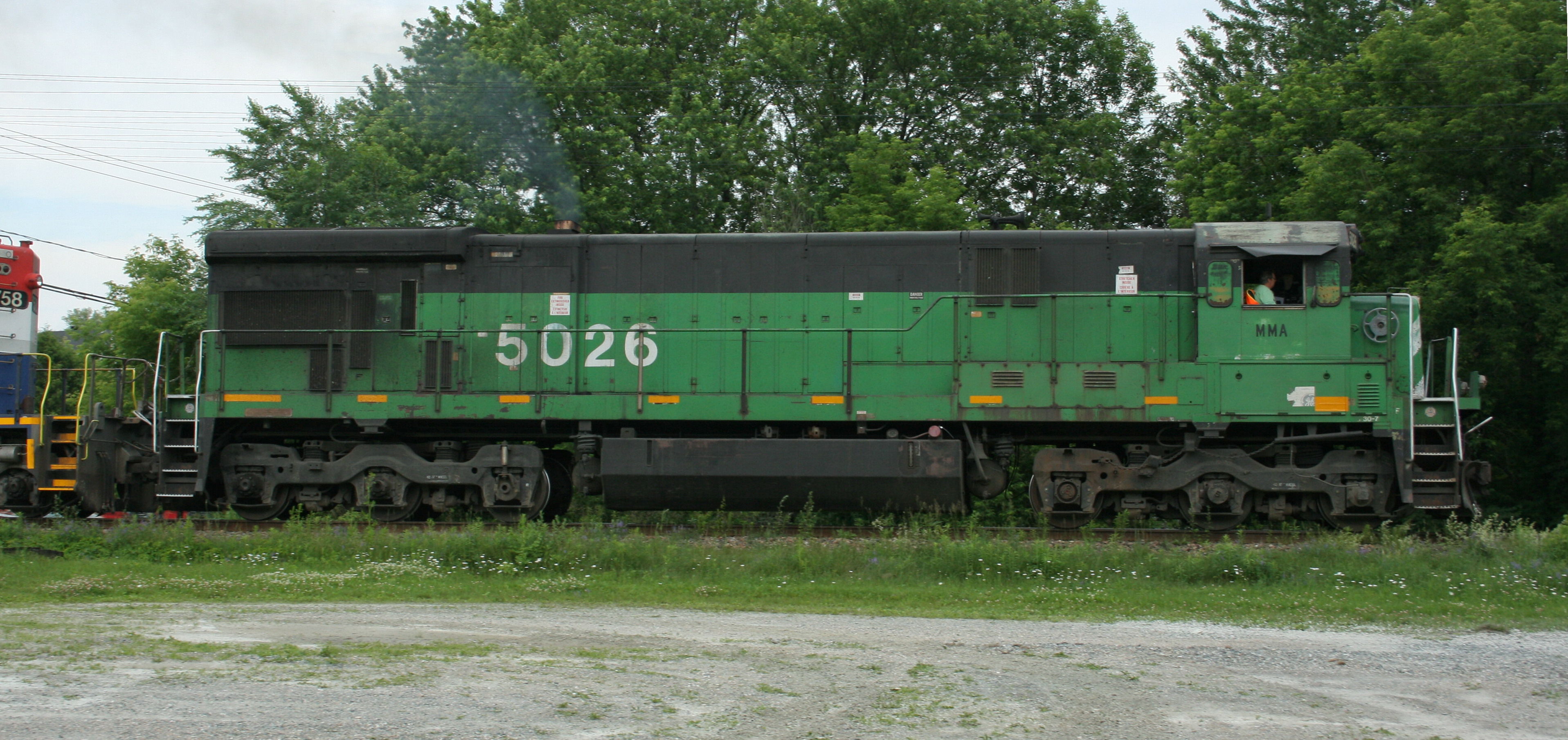
| Broadside views of MMA C30-7's #5023 and #5026, former Burlington Northern Phase 1c units seen in 2010. | |
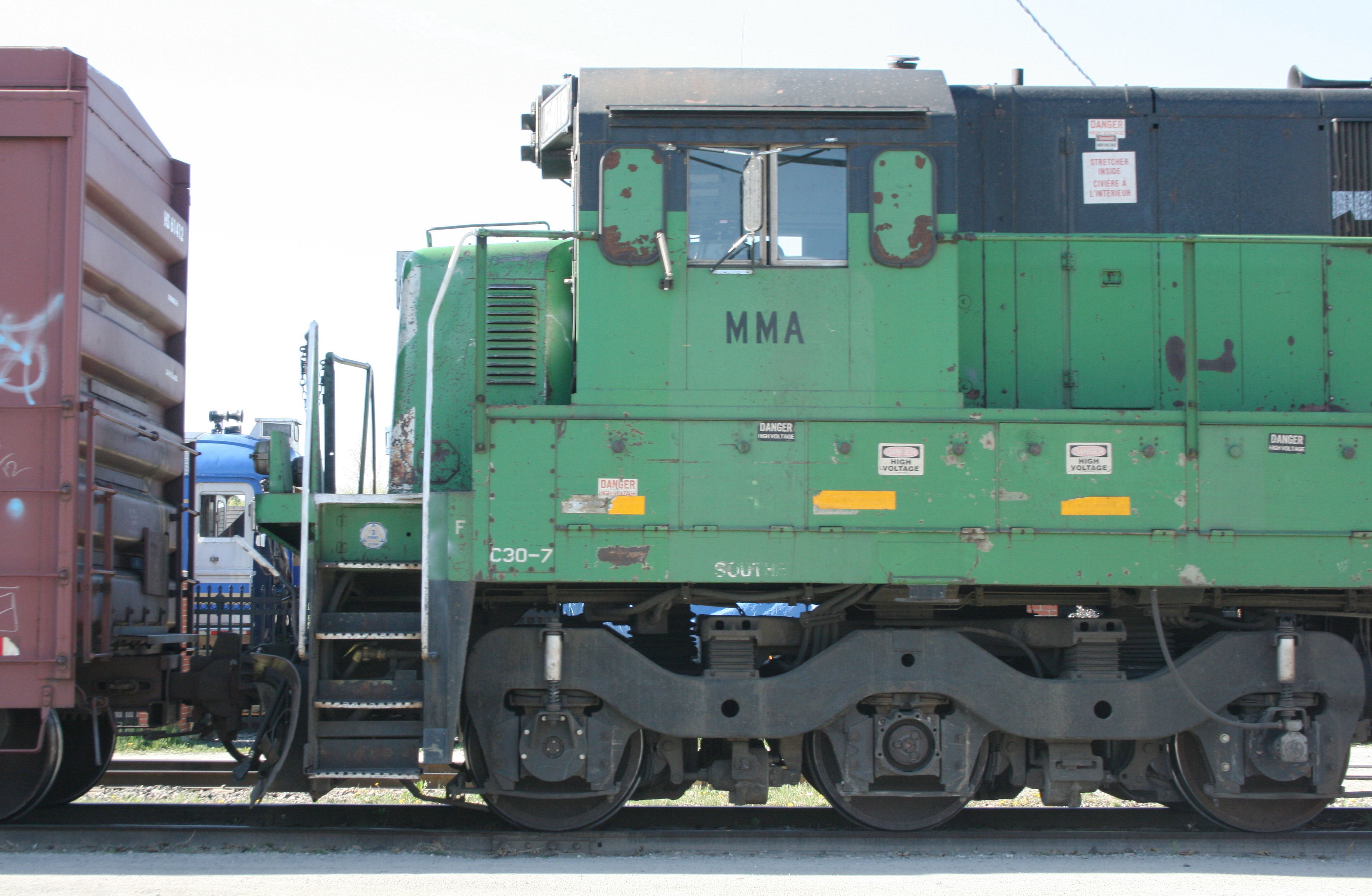
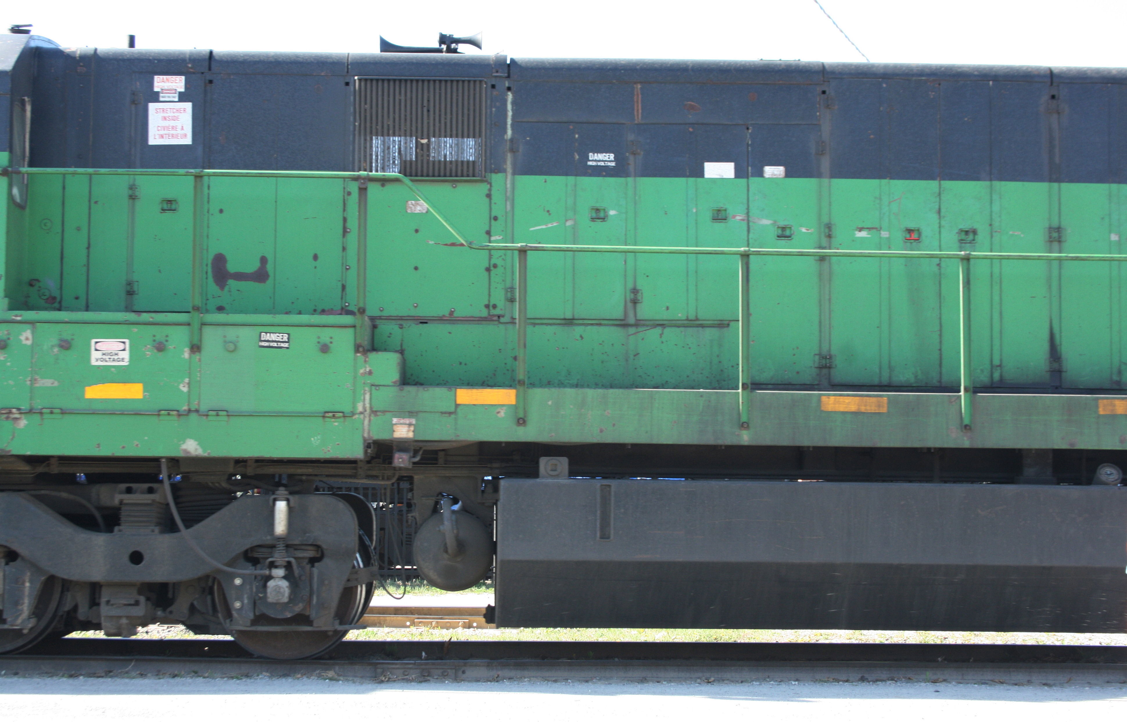


Detail photos showing the conductor's side of MMA #5018 (Phase 1c). |


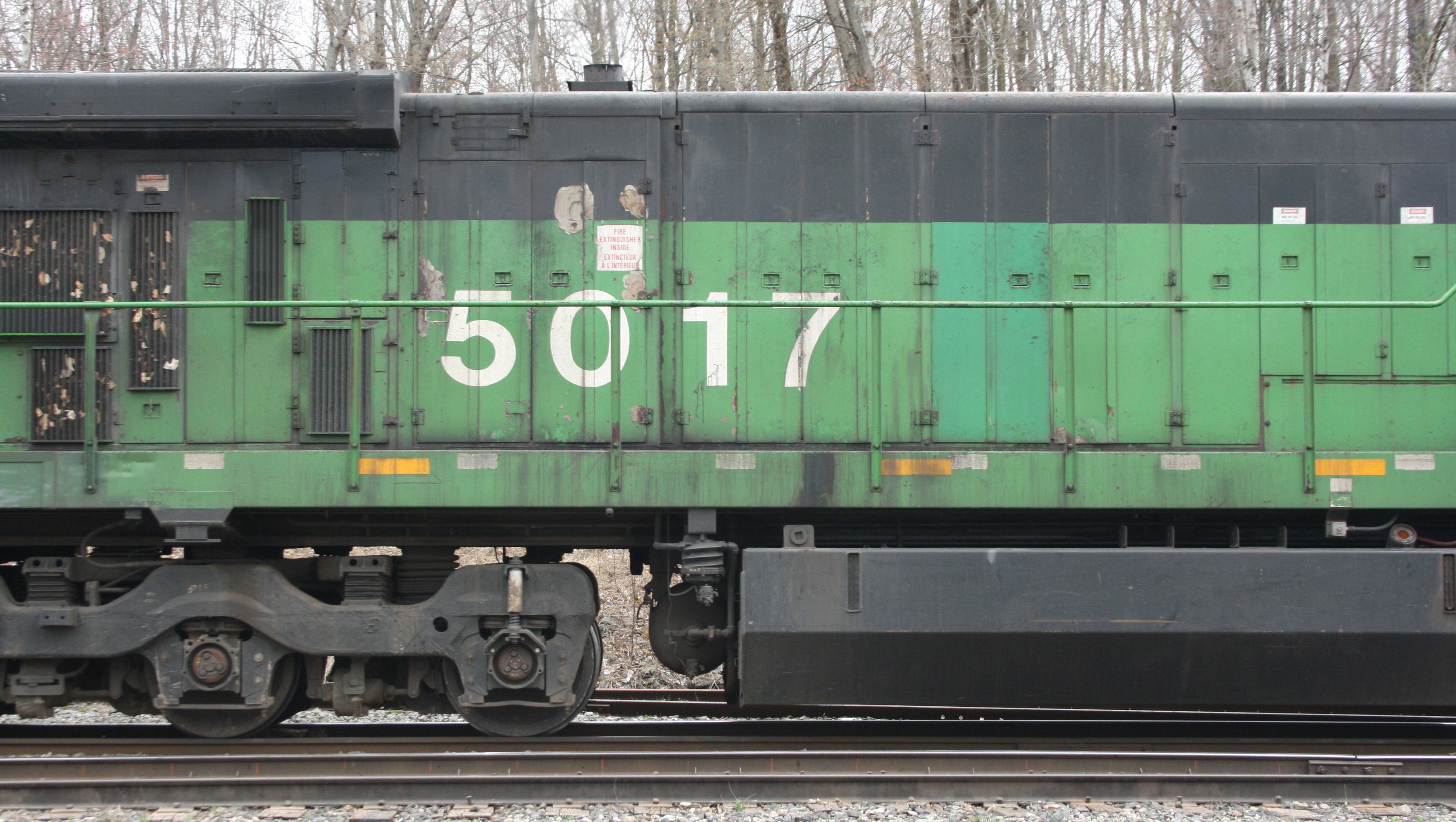

Detail photos showing the engineer's side of MMA #5017 (Phase 1c). |
 
Rockwell (top, MMA #5016) and Adirondack (bottom, MMA #5017) FB-3 trucks with low-mounted brake cylinders 
An overhead side view of the cab on MMA #3609, originally ATSF #8040. The tabs at the front of the cab roof would have originally supported a Prime 8901 amber beacon. The box on the rear of the cab roof is a ground plane for the antenna. |

Overhead view of MMA #5017 (ex-BN, Phase 1c) showing the radiator section at the rear and the clean roofline, with the break in the hood width visible just ahead of the exhaust stack. 
Overhead view of MMA #5023 (ex-BN, Phase 1c). |
See the Photos section for more photos.
References
Biel, Charles. (2005). The BNSF Photo Archive - GE C30-7. Retrieved December 2019 from http://www.trainpix.com/bnsf/GEORIG/C30-7/INDEX.HTM
Davis, W. (2014). General Electric's 1977 Series Locomotives. Retrieved December 2019 from http://railroadlocomotives.blogspot.com/2014/01/general-electrics-1977-series.html
Foster, Gerald. (1996). A Field Guide to Trains. New York, NY: Houghton Mifflin.
General Electric. Locomotive Service Manual for Series-7 Road Locomotives. GEK-30150, 1978-08.
Sarberenyi, R. GE's C36-7 - Original Owners. Retrieved December 2019 from http://www.trainweb.org/jaydeet/c36-7.htm
The Diesel Shop. (2011). General Electric C30-7 and C30-7A. Retrieved December 2016 from http://thedieselshop.us/GE_C30-7.HTML.